Project Simubot: Simulated Warehouse Management System
Warehouse Management System simulation coordinating robots, transmitting messages and defining state machines.
Project Simubot creates simulated warehouses incorporating bots which ingress stock into storage, and then either charging, parking, or picking up stock to take to an egress point.
This demonstrates the modelling of the warehouses using a game level editor called Sprite Fusion, simulating a layout in a warehouse using NetLogo to test how many robots can be used, how quickly it can be done, how stable the setup is, how many chargers are required, how fast the bots discharge, etc.
The simulation is a way of testing various configurations of warehouses with various numbers of bots and various rates of intake and outtake of stock.
The solution presented is an initial start. An attempt to define an architecture making it simple to simulate warehouse configurations and their performance under various simulated scenarios.
Goals
-
Create a simulation for a problem space that is unknown to me. I original created this simulation to understand a problem space with which I have never worked: logistically managing robots on a warehouse floor. Warehouse Management Systems is the broader term.
-
Test whether it is feasible to transfer a simulation to a production environment. Having created a working simulation, how to best transfer that to a production setup, is that possible?
-
Combine tools into a complicate architecture that no AI would have come up with. In an age where coding has become an automated robot task, humans are left to use their creativity to create overly complicated architectures to solve problems that don’t exist.
The second part of this mini project will be the application of a simulation to the real world. How to integrate the simulation into a production system without modification. For that, events from NetLogo are pushed into an MQTT message bus to confirm robot movement. Aim is running a simulation in the real world; we wanted to push out events to say, “Me, Bot A is going to move from X to Y. Is that okay?” We confirm that, and the confirmation of that movement is then shown in the simulation.
Terminology
A warehouse floor is divided up into patches. Each patch has exit points: north, east, west, south. These are defined in the design of the warehouse in the level editor. The warehouse also has stations, which provide the ingress and egress of stock. A warehouse has parking and storage elements.
All of these components can be modelled in the designer and simulator. This is a simplification and there are many more components that make up a warehouse.
Out of scope
What is not shown is the glue code between Sprite Fusion and NetLogo. There’s a step which converts the exported data from NetLogo to what we can use in Node-RED, and that’s automated by Node-RED. Also, what is not shown is the state machine of the bots. So there’s a state machine defined in Node-RED for robots, and that state machine defines the behaviour of a bot.
At this stage, it’s a very simple state machine as the bots are a modelled to be simple. They basically pick up stock, put stock into storage, then can charge themselves, they can park, and then they can take stock out of storage and bring it to the exit points. So that’s all these bots can do at this stage.
The overall architecture has not be fleshed out and instead focus is on the components and their responsibilities. A gradual fleshing out of the architecture will be done with experience and requirements.
Motivation
Besides gaining an initial understanding of the problem space of warehouse management, why this entire project?
Modelling robots as agents and to figure out how (if at all) they could work independently of one another.
What approaches are available for managing robots on a warehouse floor? These are limitless forms however three basic approaches exist:
-
A central brain that controls all movements of all bots;
-
an anarchistic form where bots are completely independent and tasks are communicated directly to these bots;
-
mixture of those two. There’s a certain amount of independence that the bots have, but there’s also a controlling instance that ensures that the entire warehouse is working.
The central brain solution has a scaling issue and the anarchistic form has a safety issue. A central brain can only coordinate so many robots before the time taken to plan and move robots takes longer than the movement of robots causing robots to pause unnecessarily.
A safety issue arises as all robots need to be informed if the warehouse is on fire. Or some other centrally caused issue needs to be communicated to all bots.
In this simulation the bots organise their own movements but are assigned tasks centrally.
Warehouse Design - Sprite Fusion
The first video shows the construction of the warehouse floor using Sprite Fusion, a level editor. It has several layers. Each layer represents one characteristic of the warehouse.
We begin with a floor, which is just a grey rectangle. We add parking spaces where the bots can park if these start to idle. Storage elements are added to store stock in the warehouse. Chargers to enable bots to charge themselves autonomously. These are placed randomly on the warehouse floor. Stations are added for stock ingress and egress.
The warehouse is split up into patches and the movement layer defines all possible movements for each patch. Each patch is assigned a definition of its exit direction: north, east, south and west.
Thus we can add corridors to the stations so that the bots will naturally flow towards the station via well defined pathways. Else, bots can create traffic jams thereby causing unnecessary congestion in moving towards stations. Predefined lanes are defined from the exit and entry points for each station to prevent congestion.
Each station has entry and exit points. These are where the bots move to first before entering the station, and exit via when leaving the station. We can model these and define the floor layout so that lanes are created along which the bots will move when they travel to stations. That’s what is being modelled in Sprite Fusion.
What we also do is we define the entry point to be three patches east. That means it’s actually located three patches east of the station, and that’s where the bot first moves to. When it moves to the station. The bot state machine defines rules such that the bot first moves to an entry point before moving to the station. The bot, wherever it is, moves first to the entry point of the station. Once it reaches that point, it then moves towards the station.
Every element of the warehouse floor has an entry and exit point, that is we add the entry and exit points to the storage patches, to the charger patches, and to all the stations. There are default entry and exit points defined if none are explicitly set on the component. For the parking spots there aren’t any entry and exit points; the implicitly defined entry and exit points are used.
We design the warehouse floor using different sprites as indicators of different features of a particular element in the warehouse. These sprites are designed to be layered on top of each other and still be visible. Because of the way Sprite Fusion works, each characteristic of a patch is also placed in a different layer. Sprite Fusion exports a JSON for each layer, thus there are multiple bits of information for a patch spread across several JSON files. These JSONs are then combined into a single JSON by Node-RED.
Once the configuration is exported from Sprite Fusion, there is a task in Node-RED that will actually generate the JSON files that we need for NetLogo. Between exporting from Sprite Fusion and using the layout in NetLogo, there’s an extra conversion step which hasn’t been shown.
This warehouse is just a random test and its construction demonstrates how the entire setup works. There are many constraints placed on the design of a warehouse, most of which have not been taken into account. For example, this simulation does not organise stock according to popularity: to avoid congestion, stock is spread across the storage elements so that robots don’t queue at particular storage points when gathering stock to fulfil an order.
Warehouse Simulation - NetLogo
Once the warehouse has been designed, the design is loaded into NetLogo. We can define the number of bots; we can define the memory of the bots - how many steps bots remember to prevent loops when moving. We can define the rate of discharge per step for bots. Bots die when they discharge fully without reaching a charger point first.
One usage of the simulation is to take a large number of bots and watching them all die. This can help to define the number of bots a particular design will support.
Ingress and egress of stock are simulated. Chargers are simulated and the bots have to coordinate their movements. If bots begin to die, then there is either too much congestion or something else is going wrong. Eventually the number of bots will level out to an amount that is naturally supported by the design.
Basically what we do is overfill the warehouse layout, run simulations until the bots start dying. Eventually there is an equilibrium of alive bots and stock in the warehouse. Thus we get a rough estimate for the optimal number of bots that you can use for the simulated warehouse layout.
Investigating the premature death of bots. Perhaps there needs to be more chargers; maybe the stations are causing congestion and the bots are getting jammed and can’t move. There are many reasons why a certain configuration of a factory or warehouse does not support as many bots as one would like.
There is iteration whereby the design of a warehouse is iterated over, tested, simulated, checked again, corrected, and simulated again, et cetera. So that’s the simulation step until a configuration is as desired. And desired means that the egress stations are constantly being supplied with stock, and the ingress stations are being cleared of stock as these are being filled.
External Sensoring - Node-RED
This video demonstrates the external connection to NetLogo. This is achieved using NetLogos internal the HubNet protocol. HubNet is a communications protocol used to link multiple NetLogos instances together. In this setup, the HubNet protocol is instead used to transport messages describing the bots’ movements via Node-RED.
How I reverse engineered the HubNet protocol is documented separately.
The intention is to be able to take a simulation and test it in the real world. To test a simulation in the real world, we need to have external sensoring via bidirectional event broadcasting between NetLogo and existing robots.
Here the connection between Node-RED and NetLogo is used to transport commands onto a MQTT message bus - using Mosquitto as broker. The idea is that before a bot moves, it sends out a message to Node-RED, and Node-RED puts it onto an MQTT message bus. That message bus is also read by Erlang-RED, which then confirms the move. Once the move has been confirmed, the bot will be moved in the NetLogo simulation.
The bots in our simulation become red when they are actually waiting on a confirmation. Once they turn green, they move, and that’s the confirmation for that move. Then they go red again to wait for the next confirmation, and so on. The video shows those messages being passed between Node-RED and Erlang-Red via the MQTT nodes.
Thus we simulate a real-world situation where bots are controlled by the simulation created in NetLogo. Bots do not move in infinitely short or non-trivial time frames. As a result, the simulation becomes as fast as the real world. A bot takes its time to move from one patch to another.
Production Simulation - Erlang-Red
We can repeat the simulation of the same warehouse layout using fewer bots, thus the movement of the individual bots becomes somewhat faster. The number of messages being sent is reduced as the number of bots has been reduced, and thus the simulation is moderately faster.
Again, it shows that the messages are arriving in Node-RED and being passed onto the MQTT bus. It is clear that the external communication does slow down the simulation.
But the idea is being able to easily take a simulation that seems to be working and has been tested in NetLogo, and take exactly the same simulation to control real bots with that. That was the intention. It might not be the best thing to do, but taking a simulation and putting it into production is a non-trivial activity.
Having the simulation also be the brain for the production system is a workaround that might work. It’s worth investigating if that is possible, and that’s what this project was doing: trying to investigate how realistic it is to be able to take a simulation and just transfer that to production.
What is Erlang-Red - full disclosure: it is a side project of mine.
Takeaways
-
I have gained a far better understanding of the problem space of coordinating robots inside a warehouse setting. Including edge cases that normally are experienced when deploying systems into the real world. Creating a simulation is a good first step to understanding new problem spaces.
-
How does a simulation become production? How do you test that? How do you finalise the testing of a solution or a simulation that might work well in production? The importance of creating a simulation, which could then become part of the production system. This is a non-trivial step but which can lead to many benefits.
-
Learning and experimenting is something that, especially in today’s AI world, is still very relevant. We need to try things out. I might have not bothered doing this and I might have well gone, “Okay, well, I’m sure there’s no better solution, and there is only one solution.” Instead, I wanted to know and find out how and why the solution is the way it is. In creating a new solution, I’ve also made the same experiences and the same learnings that other people who originally created these systems have made. I have run into walls and fallen into potholes that others already have, hence I have extended my horizon of knowledge. Even if this might end up being a throwaway project, I’ve learned much of NetLogo and Sprite Fusion (new technologies for me), these learnings might well become useful and relevant for other future projects.
Extras - Glue Code
State Machine Definitions in Node-RED
The glue code that holds this together is defined using Node-RED, first the state machine that is defined as nodes inside Node-RED.
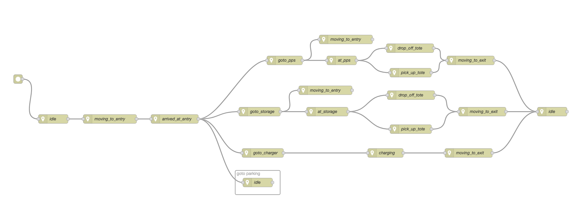
That is state machine definition is transformed into a JSON file that is ingested by NetLogo to create dynamic code. To change the bot behaviour, the NetLogo only needs restarting.
Transform Sprite Fusion JSONs to NetLogo JSONs
Sprite Fusion creates a ZIP file containing one JSON per layer. Each layer represents a particular attribute of a patch which defines the warehouse floor.
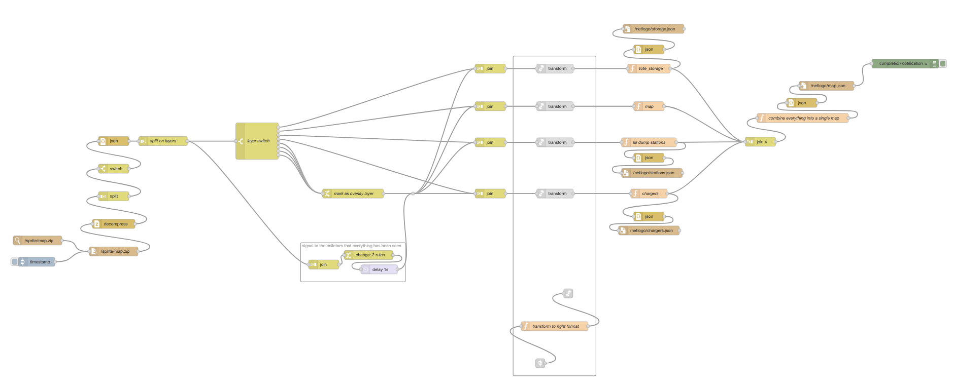
The flow works by watching for changes to the exported ZIP file (on disk). Changes trigger the flow to regenerate the NetLogo JSON files. This means that exporting a design from Sprite Fusion is all that is required to create a new layout in NetLogo.
AI Assisted content. AI aided in the creation of this article not in the construction of the architecture. The underlying codified architecture is purely the result of human intelligence (or lack thereof).
Comments powered by giscus
The author is available for Node-RED development and consultancy.