Refactoring Node-RED flows: Duplicate computation
Node-RED is flow-based visual programming, which requires a new way of thinking when it comes to refactoring and programming generally.
Node-RED models data flows between computational nodes. The lines represent the flow of data and the large colourful rectangles are the computational components, i.e., nodes.
Import to note, data flows from left to right: the left side of a node is the input side and the right side is the output node. I have indicated this by using arrows on the input side, the Node-RED editor does not have arrows so these are only here for presentational purposes.
Data may be altered by the nodes and all alterations are passed down the flow. A node may only have zero or one input but many outputs. Each output, i.e. line out of a node, is a duplication of the data object returned by the node.
This means that each node has its own copy of the data. Which implies that data objects should not be excessive in size since duplication, i.e. cloning, costs time and memory.
Note: I use Node-RED version 3.0.2 for this, your mileage might vary.
Computational Duplication
I am going to deal with something that has often happened to me: copy & pasting of nodes leads to duplication of computational code, i.e. nodes.
How to deal with deal with duplication? Visual programming also aims to apply the Don’t Repeat Yourself - DRY principle, but how to handle that in a visual manner?
Starting with this flow:
[{"id":"e9368c5098b2a6af","type":"change","z":"f386259123db97af","name":" ","rules":[{"t":"set","p":"payload","pt":"msg","to":"","tot":"str"}],"action":"","property":"","from":"","to":"","reg":false,"x":588,"y":1337,"wires":[["098831663916f725"]]},{"id":"63bf2660b887417d","type":"change","z":"f386259123db97af","name":" ","rules":[{"t":"set","p":"payload","pt":"msg","to":"","tot":"str"}],"action":"","property":"","from":"","to":"","reg":false,"x":588,"y":1403,"wires":[["6b7fd7e6d4926ad0"]]},{"id":"28b852aa3daf6506","type":"delay","z":"f386259123db97af","name":" ","pauseType":"delay","timeout":"5","timeoutUnits":"seconds","rate":"1","nbRateUnits":"1","rateUnits":"second","randomFirst":"1","randomLast":"5","randomUnits":"seconds","drop":false,"allowrate":false,"outputs":1,"x":1175,"y":1337,"wires":[[]]},{"id":"250abdca19dfc05b","type":"delay","z":"f386259123db97af","name":" ","pauseType":"delay","timeout":"5","timeoutUnits":"seconds","rate":"1","nbRateUnits":"1","rateUnits":"second","randomFirst":"1","randomLast":"5","randomUnits":"seconds","drop":false,"allowrate":false,"outputs":1,"x":1175,"y":1403,"wires":[[]]},{"id":"791c7644a2e8f2ec","type":"group","z":"f386259123db97af","name":"Common Code","style":{"label":true},"nodes":["098831663916f725","6b7fd7e6d4926ad0"],"x":689,"y":1296,"w":153,"h":148},{"id":"098831663916f725","type":"function","z":"f386259123db97af","g":"791c7644a2e8f2ec","name":" ","func":"\nreturn msg;","outputs":1,"noerr":0,"initialize":"","finalize":"","libs":[],"x":766,"y":1337,"wires":[["17fbb9c06e02ef4c"]]},{"id":"6b7fd7e6d4926ad0","type":"function","z":"f386259123db97af","g":"791c7644a2e8f2ec","name":" ","func":"\nreturn msg;","outputs":1,"noerr":0,"initialize":"","finalize":"","libs":[],"x":765,"y":1403,"wires":[["10a1e5c00102f0af"]]},{"id":"0ab4edf657b31c1f","type":"group","z":"f386259123db97af","name":"Common Code","style":{"label":true},"nodes":["17fbb9c06e02ef4c","10a1e5c00102f0af"],"x":906,"y":1296,"w":152,"h":148},{"id":"17fbb9c06e02ef4c","type":"function","z":"f386259123db97af","g":"0ab4edf657b31c1f","name":" ","func":"\nreturn msg;","outputs":1,"noerr":0,"initialize":"","finalize":"","libs":[],"x":982,"y":1337,"wires":[["28b852aa3daf6506"]]},{"id":"10a1e5c00102f0af","type":"function","z":"f386259123db97af","g":"0ab4edf657b31c1f","name":" ","func":"\nreturn msg;","outputs":1,"noerr":0,"initialize":"","finalize":"","libs":[],"x":982,"y":1403,"wires":[["250abdca19dfc05b"]]}]
Here we have two yellow nodes that represent two different states that both flow to a purple node. Between them are two orange nodes respectively. The orange nodes are duplication of the same computation.
How to handle the duplication?
An initial idea would be to do something like this:
[{"id":"20faececf507410a","type":"change","z":"f386259123db97af","name":" ","rules":[{"t":"set","p":"payload","pt":"msg","to":"","tot":"str"}],"action":"","property":"","from":"","to":"","reg":false,"x":596,"y":1553,"wires":[["0ccc2fec1466a1dc"]]},{"id":"f5eb34aa7812a560","type":"change","z":"f386259123db97af","name":" ","rules":[{"t":"set","p":"payload","pt":"msg","to":"","tot":"str"}],"action":"","property":"","from":"","to":"","reg":false,"x":596,"y":1619,"wires":[["0ccc2fec1466a1dc"]]},{"id":"88224e0dc84bc016","type":"delay","z":"f386259123db97af","name":" ","pauseType":"delay","timeout":"5","timeoutUnits":"seconds","rate":"1","nbRateUnits":"1","rateUnits":"second","randomFirst":"1","randomLast":"5","randomUnits":"seconds","drop":false,"allowrate":false,"outputs":1,"x":1183,"y":1553,"wires":[[]]},{"id":"acb3e0fcbbffac6a","type":"delay","z":"f386259123db97af","name":" ","pauseType":"delay","timeout":"5","timeoutUnits":"seconds","rate":"1","nbRateUnits":"1","rateUnits":"second","randomFirst":"1","randomLast":"5","randomUnits":"seconds","drop":false,"allowrate":false,"outputs":1,"x":1183,"y":1619,"wires":[[]]},{"id":"8110ce244458e8f7","type":"function","z":"f386259123db97af","d":true,"name":" ","func":"\nreturn msg;","outputs":1,"noerr":0,"initialize":"","finalize":"","libs":[],"x":774,"y":1553,"wires":[[]]},{"id":"0ccc2fec1466a1dc","type":"function","z":"f386259123db97af","name":" ","func":"\nreturn msg;","outputs":1,"noerr":0,"initialize":"","finalize":"","libs":[],"x":773,"y":1619,"wires":[["c1844fd93cb981af"]]},{"id":"57c6ee0c08f490b9","type":"function","z":"f386259123db97af","d":true,"name":" ","func":"\nreturn msg;","outputs":1,"noerr":0,"initialize":"","finalize":"","libs":[],"x":990,"y":1553,"wires":[[]]},{"id":"c1844fd93cb981af","type":"function","z":"f386259123db97af","name":" ","func":"\nreturn msg;","outputs":1,"noerr":0,"initialize":"","finalize":"","libs":[],"x":990,"y":1619,"wires":[["acb3e0fcbbffac6a","88224e0dc84bc016"]]}]
(Note: dashed nodes are disabled nodes and can be removed in this case.)
Node-RED does not allow us to specify which output flow to take: all output is passed to all connected nodes.
Here the problem becomes how to select the correct purple node after doing the common computation?
[{"id":"bb63d5815565d539","type":"change","z":"f386259123db97af","name":" ","rules":[{"t":"set","p":"payload","pt":"msg","to":"","tot":"str"}],"action":"","property":"","from":"","to":"","reg":false,"x":612,"y":1740,"wires":[["26042b1517092cca"]]},{"id":"079ae13af58dd942","type":"change","z":"f386259123db97af","name":" ","rules":[{"t":"set","p":"payload","pt":"msg","to":"","tot":"str"}],"action":"","property":"","from":"","to":"","reg":false,"x":612,"y":1806,"wires":[["26042b1517092cca"]]},{"id":"26042b1517092cca","type":"function","z":"f386259123db97af","name":" ","func":"\nreturn msg;","outputs":1,"noerr":0,"initialize":"","finalize":"","libs":[],"x":789,"y":1806,"wires":[["3ba9f08d5df9fd94"]]},{"id":"f8da65e8a23b618a","type":"group","z":"f386259123db97af","name":"Which output to take?","style":{"label":true},"nodes":["d58452dbb630307e","abd030eb73383077","3ba9f08d5df9fd94"],"x":930,"y":1699,"w":345,"h":148},{"id":"d58452dbb630307e","type":"delay","z":"f386259123db97af","g":"f8da65e8a23b618a","name":" ","pauseType":"delay","timeout":"5","timeoutUnits":"seconds","rate":"1","nbRateUnits":"1","rateUnits":"second","randomFirst":"1","randomLast":"5","randomUnits":"seconds","drop":false,"allowrate":false,"outputs":1,"x":1199,"y":1740,"wires":[[]]},{"id":"abd030eb73383077","type":"delay","z":"f386259123db97af","g":"f8da65e8a23b618a","name":" ","pauseType":"delay","timeout":"5","timeoutUnits":"seconds","rate":"1","nbRateUnits":"1","rateUnits":"second","randomFirst":"1","randomLast":"5","randomUnits":"seconds","drop":false,"allowrate":false,"outputs":1,"x":1199,"y":1806,"wires":[[]]},{"id":"3ba9f08d5df9fd94","type":"function","z":"f386259123db97af","g":"f8da65e8a23b618a","name":" ","func":"\nreturn msg;","outputs":1,"noerr":0,"initialize":"","finalize":"","libs":[],"x":1006,"y":1806,"wires":[["abd030eb73383077","d58452dbb630307e"]]}]
Diverting flows is possible using nodes with two or more output connectors. Nodes have one input but can have multiple output connectors not to be confused with output connections.
One solution could be to set a flag somewhere further up the flow and then have a switch node make divert the flow according to that flag:
(Note: setting a flag in Node-RED terms means adding an attribute to the data object passing allow the flow. This modified data object arrives at the switch node.)
[{"id":"c8f21a7bebfceedb","type":"function","z":"f386259123db97af","name":" ","func":"\nreturn msg;","outputs":1,"noerr":0,"initialize":"","finalize":"","libs":[],"x":771,"y":2007,"wires":[["847e689095cb39d5"]]},{"id":"819047e9b44ea731","type":"delay","z":"f386259123db97af","name":" ","pauseType":"delay","timeout":"5","timeoutUnits":"seconds","rate":"1","nbRateUnits":"1","rateUnits":"second","randomFirst":"1","randomLast":"5","randomUnits":"seconds","drop":false,"allowrate":false,"outputs":1,"x":1192,"y":1941,"wires":[[]]},{"id":"f196b86a4a17f4be","type":"delay","z":"f386259123db97af","name":" ","pauseType":"delay","timeout":"5","timeoutUnits":"seconds","rate":"1","nbRateUnits":"1","rateUnits":"second","randomFirst":"1","randomLast":"5","randomUnits":"seconds","drop":false,"allowrate":false,"outputs":1,"x":1192,"y":2007,"wires":[[]]},{"id":"847e689095cb39d5","type":"function","z":"f386259123db97af","name":" ","func":"\nreturn msg;","outputs":1,"noerr":0,"initialize":"","finalize":"","libs":[],"x":904,"y":2007,"wires":[["8acafe9c0af47989"]]},{"id":"8acafe9c0af47989","type":"switch","z":"f386259123db97af","name":"","property":"payload","propertyType":"msg","rules":[{"t":"eq","v":"","vt":"str"},{"t":"eq","v":"","vt":"str"}],"checkall":"true","repair":false,"outputs":2,"x":1046,"y":2000,"wires":[["819047e9b44ea731"],["f196b86a4a17f4be"]]},{"id":"794eedd1cdd85987","type":"group","z":"f386259123db97af","name":"Set flag","style":{"label":true},"nodes":["cc05566a7c313b2d","aa0feec9fb00ba10"],"x":529,"y":1900,"w":172,"h":148},{"id":"cc05566a7c313b2d","type":"change","z":"f386259123db97af","g":"794eedd1cdd85987","name":" flag = 1","rules":[{"t":"set","p":"payload","pt":"msg","to":"","tot":"str"}],"action":"","property":"","from":"","to":"","reg":false,"x":615,"y":1941,"wires":[["c8f21a7bebfceedb"]]},{"id":"aa0feec9fb00ba10","type":"change","z":"f386259123db97af","g":"794eedd1cdd85987","name":" flag = 2","rules":[{"t":"set","p":"payload","pt":"msg","to":"","tot":"str"}],"action":"","property":"","from":"","to":"","reg":false,"x":615,"y":2007,"wires":[["c8f21a7bebfceedb"]]}]
A switch node has multiple output connectors and represents an if .. then .. else .. programmatic statement, in this case if flag == 1 then take top flow else bottom flow.
A switch as one output connector per if-clause. So if we had a third value for the flag, then our switch would have three output connectors. Something like this pseudo code:
if flag == 1 then output-connector-1
if flag == 2 then output-connector-2
else output-connector-3
Then the switch would like this:
[{"id":"3ba545875665d33d","type":"switch","z":"f386259123db97af","name":"","property":"payload","propertyType":"msg","rules":[{"t":"eq","v":"","vt":"str"},{"t":"eq","v":"","vt":"str"},{"t":"eq","v":"","vt":"str"}],"checkall":"true","repair":false,"outputs":3,"x":1182,"y":1136,"wires":[[],[],[]]}]
This approach is one approach to solving computational duplication, there are others.
Commonality comes first
An alternative approach is sometimes to perform commonality before the specifics:
[{"id":"22b947cb47124601","type":"function","z":"f386259123db97af","name":" ","func":"\nreturn msg;","outputs":1,"noerr":0,"initialize":"","finalize":"","libs":[],"x":637,"y":2224,"wires":[["4f4dc9196103ed4a"]]},{"id":"a5c4a456ba2ee664","type":"delay","z":"f386259123db97af","name":" ","pauseType":"delay","timeout":"5","timeoutUnits":"seconds","rate":"1","nbRateUnits":"1","rateUnits":"second","randomFirst":"1","randomLast":"5","randomUnits":"seconds","drop":false,"allowrate":false,"outputs":1,"x":1204,"y":2192,"wires":[[]]},{"id":"2512a2180429ea79","type":"delay","z":"f386259123db97af","name":" ","pauseType":"delay","timeout":"5","timeoutUnits":"seconds","rate":"1","nbRateUnits":"1","rateUnits":"second","randomFirst":"1","randomLast":"5","randomUnits":"seconds","drop":false,"allowrate":false,"outputs":1,"x":1204,"y":2258,"wires":[[]]},{"id":"4f4dc9196103ed4a","type":"function","z":"f386259123db97af","name":" ","func":"\nreturn msg;","outputs":1,"noerr":0,"initialize":"","finalize":"","libs":[],"x":770,"y":2224,"wires":[["08489a72522e79a4"]]},{"id":"08489a72522e79a4","type":"switch","z":"f386259123db97af","name":"","property":"payload","propertyType":"msg","rules":[{"t":"eq","v":"","vt":"str"},{"t":"eq","v":"","vt":"str"}],"checkall":"true","repair":false,"outputs":2,"x":912,"y":2224,"wires":[["595f3642a8f0b2b1"],["bae808b8a464bf69"]]},{"id":"595f3642a8f0b2b1","type":"change","z":"f386259123db97af","name":" ","rules":[{"t":"set","p":"payload","pt":"msg","to":"","tot":"str"}],"action":"","property":"","from":"","to":"","reg":false,"x":1063,"y":2192,"wires":[["a5c4a456ba2ee664"]]},{"id":"bae808b8a464bf69","type":"change","z":"f386259123db97af","name":" ","rules":[{"t":"set","p":"payload","pt":"msg","to":"","tot":"str"}],"action":"","property":"","from":"","to":"","reg":false,"x":1063,"y":2258,"wires":[["2512a2180429ea79"]]}]
Here the common computation is done and then the flow diverge. This could be a case of some computation that is independent of two yellow nodes and therefore can be done beforehand. This approach is also the fail early, fail fast pattern.
The flag for the switch (lots of hand-waving here) is set somewhere up further the flow!
Subflows
This approach to duplication is fine if there is only one area of duplication but what if we had two different and disconnected flows that use the same code?
[{"id":"d03c4820970ac189","type":"subflow","name":"Respond: ERROR","info":"","category":"","in":[{"x":50,"y":80,"wires":[{"id":"626e48f3cb80df01"}]}],"out":[],"env":[],"meta":{},"color":"#3FADB5","icon":"font-awesome/fa-send"},{"id":"626e48f3cb80df01","type":"function","z":"d03c4820970ac189","name":"send error","func":"msg.payload = {\n status: \"error\",\n msg: msg.error\n};\nreturn msg;","outputs":1,"noerr":0,"initialize":"","finalize":"","libs":[],"x":200,"y":80,"wires":[["3d1e8765a364c1f6","427745bac47be193"]]},{"id":"3d1e8765a364c1f6","type":"http response","z":"d03c4820970ac189","name":"","statusCode":"","headers":{},"x":433.999755859375,"y":79.99992370605469,"wires":[]},{"id":"427745bac47be193","type":"debug","z":"d03c4820970ac189","name":"ERROR RESPONSE","active":true,"tosidebar":true,"console":false,"tostatus":false,"complete":"true","targetType":"full","statusVal":"","statusType":"auto","x":436.76562881469727,"y":153.75001335144043,"wires":[]},{"id":"c420ddb0886ef6ce","type":"delay","z":"f386259123db97af","name":" ","pauseType":"delay","timeout":"5","timeoutUnits":"seconds","rate":"1","nbRateUnits":"1","rateUnits":"second","randomFirst":"1","randomLast":"5","randomUnits":"seconds","drop":false,"allowrate":false,"outputs":1,"x":1316,"y":2543,"wires":[[]]},{"id":"45cb4542ad22b6a2","type":"delay","z":"f386259123db97af","name":" ","pauseType":"delay","timeout":"5","timeoutUnits":"seconds","rate":"1","nbRateUnits":"1","rateUnits":"second","randomFirst":"1","randomLast":"5","randomUnits":"seconds","drop":false,"allowrate":false,"outputs":1,"x":1316,"y":2609,"wires":[[]]},{"id":"80e56eee07b32324","type":"switch","z":"f386259123db97af","name":" ","property":"payload","propertyType":"msg","rules":[{"t":"eq","v":"","vt":"str"},{"t":"eq","v":"","vt":"str"}],"checkall":"true","repair":false,"outputs":2,"x":1024,"y":2575,"wires":[["848b97a79084762f"],["d55106e2ee1fe0e9"]]},{"id":"848b97a79084762f","type":"change","z":"f386259123db97af","name":" ","rules":[{"t":"set","p":"payload","pt":"msg","to":"","tot":"str"}],"action":"","property":"","from":"","to":"","reg":false,"x":1175,"y":2543,"wires":[["c420ddb0886ef6ce"]]},{"id":"d55106e2ee1fe0e9","type":"change","z":"f386259123db97af","name":" ","rules":[{"t":"set","p":"payload","pt":"msg","to":"","tot":"str"}],"action":"","property":"","from":"","to":"","reg":false,"x":1175,"y":2609,"wires":[["45cb4542ad22b6a2"]]},{"id":"cd6329aea69beaec","type":"exec","z":"f386259123db97af","command":"","addpay":"","append":"","useSpawn":"false","timer":"","winHide":false,"oldrc":false,"name":" ","x":1098,"y":2754,"wires":[["b23ad924de6088c5"],["86a7af5083ddae4b"],["243ade68a1c5b0fc"]]},{"id":"76decf570e1200fa","type":"feedparse","z":"f386259123db97af","name":" ","url":" ","interval":15,"ignorefirst":false,"x":572,"y":2754.5,"wires":[["fb29e6131a17e5ae"]]},{"id":"86a7af5083ddae4b","type":"ui_toast","z":"f386259123db97af","position":"top right","displayTime":"3","highlight":"","sendall":true,"outputs":0,"ok":"OK","cancel":"","raw":false,"className":"","topic":"","name":" ","x":1319,"y":2755,"wires":[]},{"id":"243ade68a1c5b0fc","type":"ui_audio","z":"f386259123db97af","name":" ","group":"fb1f147eb5dba68c","voice":"","always":"","x":1319,"y":2800,"wires":[]},{"id":"b23ad924de6088c5","type":"subflow:d03c4820970ac189","z":"f386259123db97af","name":" ","x":1319,"y":2710,"wires":[]},{"id":"536acde789130f79","type":"group","z":"f386259123db97af","name":"Common Code","style":{"label":true},"nodes":["097e86c593f2bb81","35c3fb45a80da289","fb29e6131a17e5ae","1d89c5fbb0f013ba"],"x":673,"y":2534,"w":285,"h":261.5},{"id":"097e86c593f2bb81","type":"function","z":"f386259123db97af","g":"536acde789130f79","name":" ","func":"\nreturn msg;","outputs":1,"noerr":0,"initialize":"","finalize":"","libs":[],"x":749,"y":2575,"wires":[["35c3fb45a80da289"]]},{"id":"35c3fb45a80da289","type":"function","z":"f386259123db97af","g":"536acde789130f79","name":" ","func":"\nreturn msg;","outputs":1,"noerr":0,"initialize":"","finalize":"","libs":[],"x":882,"y":2575,"wires":[["80e56eee07b32324"]]},{"id":"fb29e6131a17e5ae","type":"function","z":"f386259123db97af","g":"536acde789130f79","name":" ","func":"\nreturn msg;","outputs":1,"noerr":0,"initialize":"","finalize":"","libs":[],"x":749,"y":2754.5,"wires":[["1d89c5fbb0f013ba"]]},{"id":"1d89c5fbb0f013ba","type":"function","z":"f386259123db97af","g":"536acde789130f79","name":" ","func":"\nreturn msg;","outputs":1,"noerr":0,"initialize":"","finalize":"","libs":[],"x":882,"y":2754.5,"wires":[["cd6329aea69beaec"]]},{"id":"fb1f147eb5dba68c","type":"ui_group","name":"Default","tab":"8d4810d71e9758dc","order":2,"disp":false,"width":"18","collapse":false,"className":""},{"id":"8d4810d71e9758dc","type":"ui_tab","name":"Mapping Information Bubble","icon":"fa-file-text-o","order":7,"disabled":false,"hidden":false}]
In this case we have two different flows that simply cannot be brought together, how do we refactor this? Enter Subflows! Subflows are a concept within Node-RED for bundling together nodes into a mini-flow, i.e., a subflow.
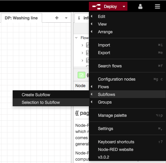
Subflows can be created by highlighting the common nodes and going to the Node-RED menu and selecting Subflows --> Selection to Subflow.

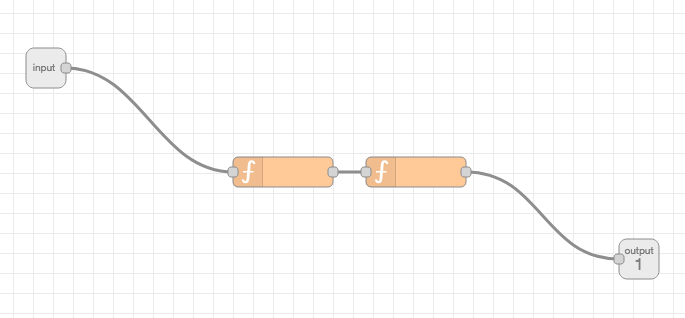
The subflow then becomes:

In the subflow editor, one can specify the number of outputs (one in this case) and whether the subflow has zero or one input (also one in this case).
Our flows become this:
[{"id":"2190b30ea37e3cf2","type":"subflow","name":"Subflow 1","info":"","in":[{"x":473,"y":375,"wires":[{"id":"a083c1c52162e6de"}]}],"out":[{"x":1066,"y":566,"wires":[{"id":"2e2b33e82c08d548","port":0}]}]},{"id":"a083c1c52162e6de","type":"function","z":"2190b30ea37e3cf2","name":" ","func":"\nreturn msg;","outputs":1,"noerr":0,"initialize":"","finalize":"","libs":[],"x":710,"y":479,"wires":[["2e2b33e82c08d548"]]},{"id":"2e2b33e82c08d548","type":"function","z":"2190b30ea37e3cf2","name":" ","func":"\nreturn msg;","outputs":1,"noerr":0,"initialize":"","finalize":"","libs":[],"x":843,"y":479,"wires":[[]]},{"id":"d03c4820970ac189","type":"subflow","name":"Respond: ERROR","info":"","category":"","in":[{"x":50,"y":80,"wires":[{"id":"626e48f3cb80df01"}]}],"out":[],"env":[],"meta":{},"color":"#3FADB5","icon":"font-awesome/fa-send"},{"id":"626e48f3cb80df01","type":"function","z":"d03c4820970ac189","name":"send error","func":"msg.payload = {\n status: \"error\",\n msg: msg.error\n};\nreturn msg;","outputs":1,"noerr":0,"initialize":"","finalize":"","libs":[],"x":200,"y":80,"wires":[["3d1e8765a364c1f6","427745bac47be193"]]},{"id":"3d1e8765a364c1f6","type":"http response","z":"d03c4820970ac189","name":"","statusCode":"","headers":{},"x":433.999755859375,"y":79.99992370605469,"wires":[]},{"id":"427745bac47be193","type":"debug","z":"d03c4820970ac189","name":"ERROR RESPONSE","active":true,"tosidebar":true,"console":false,"tostatus":false,"complete":"true","targetType":"full","statusVal":"","statusType":"auto","x":436.76562881469727,"y":153.75001335144043,"wires":[]},{"id":"76196a66e3139d9a","type":"delay","z":"f386259123db97af","name":" ","pauseType":"delay","timeout":"5","timeoutUnits":"seconds","rate":"1","nbRateUnits":"1","rateUnits":"second","randomFirst":"1","randomLast":"5","randomUnits":"seconds","drop":false,"allowrate":false,"outputs":1,"x":1319,"y":2969,"wires":[[]]},{"id":"e853cea1e5c03511","type":"delay","z":"f386259123db97af","name":" ","pauseType":"delay","timeout":"5","timeoutUnits":"seconds","rate":"1","nbRateUnits":"1","rateUnits":"second","randomFirst":"1","randomLast":"5","randomUnits":"seconds","drop":false,"allowrate":false,"outputs":1,"x":1319,"y":3035,"wires":[[]]},{"id":"72c00247ddba1bcd","type":"switch","z":"f386259123db97af","name":" ","property":"payload","propertyType":"msg","rules":[{"t":"eq","v":"","vt":"str"},{"t":"eq","v":"","vt":"str"}],"checkall":"true","repair":false,"outputs":2,"x":1027,"y":3001,"wires":[["af74104ddcbb53ea"],["f21745c03eb41b5a"]]},{"id":"af74104ddcbb53ea","type":"change","z":"f386259123db97af","name":" ","rules":[{"t":"set","p":"payload","pt":"msg","to":"","tot":"str"}],"action":"","property":"","from":"","to":"","reg":false,"x":1178,"y":2969,"wires":[["76196a66e3139d9a"]]},{"id":"f21745c03eb41b5a","type":"change","z":"f386259123db97af","name":" ","rules":[{"t":"set","p":"payload","pt":"msg","to":"","tot":"str"}],"action":"","property":"","from":"","to":"","reg":false,"x":1178,"y":3035,"wires":[["e853cea1e5c03511"]]},{"id":"4156b71363cfc97d","type":"exec","z":"f386259123db97af","command":"","addpay":"","append":"","useSpawn":"false","timer":"","winHide":false,"oldrc":false,"name":" ","x":1101,"y":3180,"wires":[["b859436c2a7431fa"],["c7ba6105f3367928"],["7507956adf1e91a8"]]},{"id":"edae2bc4e33d53c5","type":"feedparse","z":"f386259123db97af","name":" ","url":" ","interval":15,"ignorefirst":false,"x":688,"y":3180.5,"wires":[["3c67c7838c5df9d1"]]},{"id":"c7ba6105f3367928","type":"ui_toast","z":"f386259123db97af","position":"top right","displayTime":"3","highlight":"","sendall":true,"outputs":0,"ok":"OK","cancel":"","raw":false,"className":"","topic":"","name":" ","x":1322,"y":3181,"wires":[]},{"id":"7507956adf1e91a8","type":"ui_audio","z":"f386259123db97af","name":" ","group":"fb1f147eb5dba68c","voice":"","always":"","x":1322,"y":3226,"wires":[]},{"id":"b859436c2a7431fa","type":"subflow:d03c4820970ac189","z":"f386259123db97af","name":" ","x":1322,"y":3136,"wires":[]},{"id":"025d2545a91924d5","type":"subflow:2190b30ea37e3cf2","z":"f386259123db97af","name":"Subflow","x":875,"y":3001,"wires":[["72c00247ddba1bcd"]]},{"id":"3c67c7838c5df9d1","type":"subflow:2190b30ea37e3cf2","z":"f386259123db97af","name":"Subflow","x":872,"y":3180,"wires":[["4156b71363cfc97d"]]},{"id":"fb1f147eb5dba68c","type":"ui_group","name":"Default","tab":"8d4810d71e9758dc","order":2,"disp":false,"width":"18","collapse":false,"className":""},{"id":"8d4810d71e9758dc","type":"ui_tab","name":"Mapping Information Bubble","icon":"fa-file-text-o","order":7,"disabled":false,"hidden":false}]
The advantage of Subflows is that any modification made to them is reflected in all usages of the subflow. Meaning that if I changed the subflow to contain three nodes, then that would reflected in both flows above.
Subflows with multiple outputs
Subflows can have multiple output connectors (not to be confused with connections) and if we look at the top flow, we have the switch node:
[{"id":"b79f96c2aef7e18d","type":"subflow","name":"Subflow 2","info":"","in":[{"x":50,"y":30,"wires":[]}],"out":[{"x":160,"y":30,"wires":[]}]},{"id":"807a193528f7428d","type":"switch","z":"f386259123db97af","name":" ","property":"payload","propertyType":"msg","rules":[{"t":"eq","v":"","vt":"str"},{"t":"eq","v":"","vt":"str"}],"checkall":"true","repair":false,"outputs":2,"x":999,"y":3018,"wires":[["69a344ebed196b42"],["1e0927a0ed541848"]]},{"id":"69a344ebed196b42","type":"change","z":"f386259123db97af","name":" ","rules":[{"t":"set","p":"payload","pt":"msg","to":"","tot":"str"}],"action":"","property":"","from":"","to":"","reg":false,"x":1150,"y":2986,"wires":[[]]},{"id":"1e0927a0ed541848","type":"change","z":"f386259123db97af","name":" ","rules":[{"t":"set","p":"payload","pt":"msg","to":"","tot":"str"}],"action":"","property":"","from":"","to":"","reg":false,"x":1150,"y":3052,"wires":[[]]},{"id":"7aa63710bcad691a","type":"subflow:b79f96c2aef7e18d","z":"f386259123db97af","name":"Subflow","x":840,"y":3018,"wires":[["807a193528f7428d"]]}]
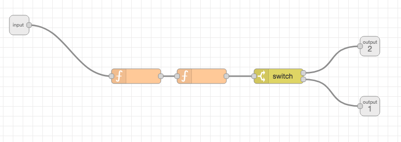
Perhaps that would be candidate for putting into our subflow and having multiple output connectors? Let’s try it.
Our subflow becomes this:

And our flows become this:
[{"id":"2190b30ea37e3cf2","type":"subflow","name":"Subflow 1","info":"","in":[{"x":473,"y":375,"wires":[{"id":"a083c1c52162e6de"}]}],"out":[{"x":1184,"y":540,"wires":[{"id":"e9869abaa67861cf","port":1}]},{"x":1184,"y":418,"wires":[{"id":"e9869abaa67861cf","port":0}]}]},{"id":"a083c1c52162e6de","type":"function","z":"2190b30ea37e3cf2","name":" ","func":"\nreturn msg;","outputs":1,"noerr":0,"initialize":"","finalize":"","libs":[],"x":710,"y":479,"wires":[["2e2b33e82c08d548"]]},{"id":"2e2b33e82c08d548","type":"function","z":"2190b30ea37e3cf2","name":" ","func":"\nreturn msg;","outputs":1,"noerr":0,"initialize":"","finalize":"","libs":[],"x":843,"y":479,"wires":[["e9869abaa67861cf"]]},{"id":"e9869abaa67861cf","type":"switch","z":"2190b30ea37e3cf2","name":"","property":"payload","propertyType":"msg","rules":[{"t":"eq","v":"","vt":"str"},{"t":"eq","v":"","vt":"str"}],"checkall":"true","repair":false,"outputs":2,"x":999,"y":479,"wires":[[],[]]},{"id":"d03c4820970ac189","type":"subflow","name":"Respond: ERROR","info":"","category":"","in":[{"x":50,"y":80,"wires":[{"id":"626e48f3cb80df01"}]}],"out":[],"env":[],"meta":{},"color":"#3FADB5","icon":"font-awesome/fa-send"},{"id":"626e48f3cb80df01","type":"function","z":"d03c4820970ac189","name":"send error","func":"msg.payload = {\n status: \"error\",\n msg: msg.error\n};\nreturn msg;","outputs":1,"noerr":0,"initialize":"","finalize":"","libs":[],"x":200,"y":80,"wires":[["3d1e8765a364c1f6","427745bac47be193"]]},{"id":"3d1e8765a364c1f6","type":"http response","z":"d03c4820970ac189","name":"","statusCode":"","headers":{},"x":433.999755859375,"y":79.99992370605469,"wires":[]},{"id":"427745bac47be193","type":"debug","z":"d03c4820970ac189","name":"ERROR RESPONSE","active":true,"tosidebar":true,"console":false,"tostatus":false,"complete":"true","targetType":"full","statusVal":"","statusType":"auto","x":436.76562881469727,"y":153.75001335144043,"wires":[]},{"id":"76196a66e3139d9a","type":"delay","z":"f386259123db97af","name":" ","pauseType":"delay","timeout":"5","timeoutUnits":"seconds","rate":"1","nbRateUnits":"1","rateUnits":"second","randomFirst":"1","randomLast":"5","randomUnits":"seconds","drop":false,"allowrate":false,"outputs":1,"x":1294,"y":3231,"wires":[[]]},{"id":"e853cea1e5c03511","type":"delay","z":"f386259123db97af","name":" ","pauseType":"delay","timeout":"5","timeoutUnits":"seconds","rate":"1","nbRateUnits":"1","rateUnits":"second","randomFirst":"1","randomLast":"5","randomUnits":"seconds","drop":false,"allowrate":false,"outputs":1,"x":1294,"y":3297,"wires":[[]]},{"id":"af74104ddcbb53ea","type":"change","z":"f386259123db97af","name":" ","rules":[{"t":"set","p":"payload","pt":"msg","to":"","tot":"str"}],"action":"","property":"","from":"","to":"","reg":false,"x":1153,"y":3231,"wires":[["76196a66e3139d9a"]]},{"id":"f21745c03eb41b5a","type":"change","z":"f386259123db97af","name":" ","rules":[{"t":"set","p":"payload","pt":"msg","to":"","tot":"str"}],"action":"","property":"","from":"","to":"","reg":false,"x":1153,"y":3297,"wires":[["e853cea1e5c03511"]]},{"id":"4156b71363cfc97d","type":"exec","z":"f386259123db97af","command":"","addpay":"","append":"","useSpawn":"false","timer":"","winHide":false,"oldrc":false,"name":" ","x":1076,"y":3442,"wires":[["b859436c2a7431fa"],["c7ba6105f3367928"],["7507956adf1e91a8"]]},{"id":"edae2bc4e33d53c5","type":"feedparse","z":"f386259123db97af","name":" ","url":" ","interval":15,"ignorefirst":false,"x":723,"y":3448.5,"wires":[["3c67c7838c5df9d1"]]},{"id":"c7ba6105f3367928","type":"ui_toast","z":"f386259123db97af","position":"top right","displayTime":"3","highlight":"","sendall":true,"outputs":0,"ok":"OK","cancel":"","raw":false,"className":"","topic":"","name":" ","x":1297,"y":3443,"wires":[]},{"id":"7507956adf1e91a8","type":"ui_audio","z":"f386259123db97af","name":" ","group":"fb1f147eb5dba68c","voice":"","always":"","x":1297,"y":3488,"wires":[]},{"id":"b859436c2a7431fa","type":"subflow:d03c4820970ac189","z":"f386259123db97af","name":" ","x":1297,"y":3398,"wires":[]},{"id":"025d2545a91924d5","type":"subflow:2190b30ea37e3cf2","z":"f386259123db97af","name":"Subflow","x":916,"y":3263,"wires":[["af74104ddcbb53ea"],["f21745c03eb41b5a"]]},{"id":"3c67c7838c5df9d1","type":"subflow:2190b30ea37e3cf2","z":"f386259123db97af","name":"Subflow","x":907,"y":3448,"wires":[["4156b71363cfc97d"],[]]},{"id":"fb1f147eb5dba68c","type":"ui_group","name":"Default","tab":"8d4810d71e9758dc","order":2,"disp":false,"width":"18","collapse":false,"className":""},{"id":"8d4810d71e9758dc","type":"ui_tab","name":"Mapping Information Bubble","icon":"fa-file-text-o","order":7,"disabled":false,"hidden":false}]
But wait! The second flow now has a dangling output connector on the subflow? What to do with it? Does the second output flow into the red node? What does the second output semantically mean?
And here in lies the disadvantage of having Subflows sharing change. The challenge of finding the balance between code commonality remains, even with a visual programming environment.
Link Nodes
There is another approach that I describe over here and that is using link in/out/call nodes. That is probably the approach that you will use most often but also a little tricky to get ones head around.
More approaches?
I am sure there more approaches (including creating nodes), if you have any ideas please send me an email.
Also this page has been created using Node-RED, click on the [Source Flow] link below to view the code behind this page!
Comments powered by giscus
The author is available for Node-RED development and consultancy.